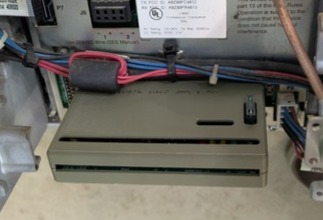
My radio club has had a VHF and a UHF MTR2000 repeater on-the-air for quite some time as part of a linked system using RoIP. The wiring interface is a cable from the radio’s System Connector (J5) to a multiport repeater controller. There’s no buffering between the radio and the controller.
I’ve read about repeater builders that have damaged their MTR2000 Station Control Module while working with external cabling connected to the System Connector. I wanted to avoid those problems during my own work and during future maintenance activities.
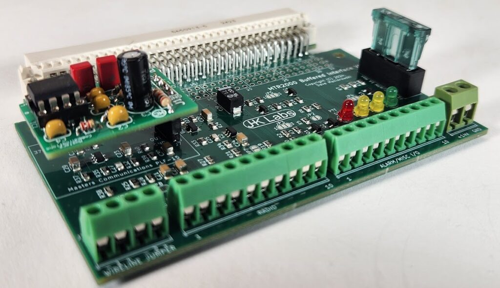
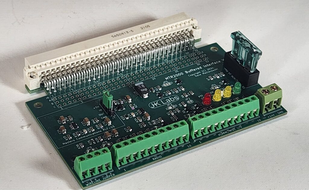
More than just a board and a couple of connectors, the MTR2000 Buffered Interface described here minimizes those risks by buffering all signaling between the System Connector (J5) and any external control equipment.
In addition to the usual station audio and control signals, the interface module also provides access to power for an external controller and to alarm and wildcard I/O. Jumper options allow customization.
Features
Radio Port Terminal Strip
- RX Audio Out
- TX Audio In
- RSSI Out
- CTCSS Encode Tone Audio In
- TX PTT Logic In
- RX COR Logic Out
- RX CTCSS Decode Logic Out
Wireline Terminal Strip
- Pair 1 +/- TX Audio In
- Pair 2 +/- RX Audio Out
Alarm and GPIO Terminal Strip
- AC Fail Logic Out
- PA Fail Logic Out (Aux I/O) *
- VSWR Fault Logic Out (Aux I/O) *
- RX LOCK Logic Out (Aux I/O) *
- TX LOCK Logic Out (Aux I/O) *
- GPO 0 Logic Out (WildCard Out, Aux I/O) *
- GPO 2 Logic Out (WildCard Out, Aux I/O) *
- GPI 3 Logic In (WildCard In, Aux I/O) *
- GPI 7 Logic In (WildCard In, Aux I/O) *
Note: * Denotes Aux I/O Board Required for Alarm and GPIO
14.2VDC Power Out Terminal Strip
- ATC Fuse (1A supplied)
Solder Jumper Options
- TX Audio In to Wireline or AUX TX In
- RX Audio Out from Wireline or RX Discriminator
- COR Logic Out Active High or Low
- CTCSS Decode Logic Out Active High or Low
- PTT Logic In Active High or Low
- PTT Logic In Pullup
- COR Logic Out Pullup
- CTCSS Decode Logic Out Pullup
- AC Fail Logic Out Pullup
Other Features
- Summing amp combines TX Audio In and CTCSS Encode Audio In to the MTR2000 AUX Tx Audio In.
- No Pots. Audio Levels adjusted with the MTR2000 RSS
- Powered from MTR2000 Internal +5VDC
- Status LEDs: PTT, COR, CTCSS, Power
- Optional: CTCSS High Pass Filter
Accepts a Masters Communications PLF-15
Configuration
Option Jumpers
- JP1: Solder to Pullup TX PTT In (Default)
- JP2: Solder to Pullup AC Fail Out
- JP3: 1-2: Low Active PTT Input (Default)
3-2: High Active PTT Input - JP4: 1-2: High Active CTCSS Out
3-2: Low Active CTCSS Out (Default) - JP5: 1-2: High Active COR Out
3-2: Low Active COR Out (Default) - JP6: Solder to Pullup RX CTCSS Decode Out
- JP7: Solder to Pullup RX COR Out
- JP8: 1-2: RP TX Audio Input to AUX TX Input (Default)
3-2: RP TX Audio Input to Wireline TX Input - JP9: 1-2: RX Disc Audio Output to RP RX Audio Output (Default)
3-2: RX Wireline Output to RP RX Audio Output
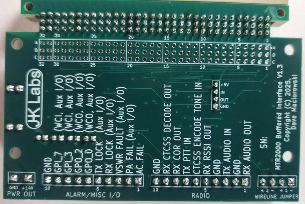
Wireline Terminal Strip
- 1: GND
- 2: TX Audio In
- 3: GND
- 4: RX Audio Out
Ref: https://www.repeater-builder.com/motorola/mtr2k/more-mtr2k-int/mtr2000-interfacing-followup.html
Radio Port (RP) Terminal Strip
- 1: RX Audio Out
- 2: GND
- 3: TX Audio In
- 4: GND
- 5: RX RSSI Analog Out
- 6: CTCSS Encode Tone Audio In
- 7: TX PTT Logic In
- 8: RX COR Logic Out
- 9: RX CTCSS Decode Logic Out
- 10: GND
Alarm/Misc I/O Terminal Strip
- 1: AC Fail Out
- 2: PA Fail Out (Aux I/O)
- 3: VSWR FAULT Out (Aux I/O)
- 4: RX LOCK Out (Aux I/O)
- 5: TX LOCK Out (Aux I/O)
- 6: GPO 0 Out (WCO, Aux I/O)
- 7: GPO 2 Out (WCO, Aux I/O)
- 8: GPI 3 In (WCI, Aux I/O)
- 9: GPI 7 In (WCI, Aux I/O)
- 10: GND
Note: Pins Marked Aux I/O Require Aux I/O Option Board
Auxiliary Power Terminal Strip
- 1: +14V Out
- 2: GND
Documentation
- Datasheet and Board Configuration Instructions
- MTR2000 Buffered Interface Configuration
- 3D Printed Case
Availability
- 6 In Stock, more on the way!!!
Pricing
- $80 (includes import tariff) plus shipping
Ordering
- Call or Email…